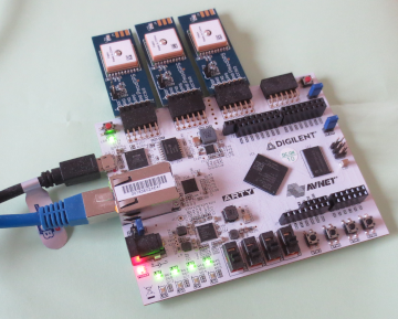
While the GPS receiver is able to work in-doors in some circumstances, the use of an outdoor antenna with a good skyview improves the satellite signals and thus the system stability. Note: antenna requires soldering of an SMA connector. (Digilent: very nice boards, but reduced score for not soldering the SMA connector.)
openFPGALoader -b arty boards/Arty_A7-35/a35_fnet/a35_fnet.bitTo write the gateware to flash storage (used after reset / powercycling), add the flag
-f.
Basic Fakernet testing is described here.
Monitor GPS UART messages and PPS pulses:
client/fnetctrl 192.168.1.192 --tcp=gps
PPS-1: 4021974195
TRACK-1: 3869485087.000000032 (:000000140) a:8983270 d: -11
UART-1: $GPGGA,165807.000,5742.7691,N,01201.3512,E,1,11,0.82,37.0,M,40.0,M,,*51
UART-1: $GPGSA,A,3,29,11,20,05,07,02,09,06,26,04,30,,1.63,0.82,1.41*0D
UART-1: $GPRMC,165807.000,A,5742.7691,N,01201.3512,E,0.01,188.11,140822,,,A*64
NEXT-1: 3869485088
UART-1: $GPVTG,188.11,T,,M,0.01,N,0.03,K,A*3E
PPS-1: 4121972906
TRACK-1: 3869485088.000000036 (:000000155) a:8983140 d: -26
UART-1: $GPGGA,165808.000,5742.7691,N,01201.3512,E,1,12,0.78,37.0,M,40.0,M,,*58
UART-1: $GPGSA,A,3,29,11,20,05,07,02,09,06,26,04,30,16,1.61,0.78,1.41*0D
UART-1: $GPGSV,4,1,14,07,62,160,37,20,54,283,34,09,52,091,42,11,38,246,32*7E
UART-1: $GPGSV,4,2,14,30,36,196,35,02,35,279,24,16,22,043,16,05,21,305,15*79
UART-1: $GPGSV,4,3,14,06,19,211,16,04,16,085,16,29,11,324,25,44,09,122,*78
UART-1: $GPGSV,4,4,14,26,08,021,26,13,01,258,*7B
UART-1: $GPRMC,165808.000,A,5742.7691,N,01201.3512,E,0.02,188.11,140822,,,A*68
NEXT-1: 3869485089
UART-1: $GPVTG,188.11,T,,M,0.02,N,0.03,K,A*3D
PPS-1: 4221971616
TRACK-1: 3869485089.000000024 (:000000107) a:8983250 d: 22
UART-1: $GPGGA,165809.000,5742.7691,N,01201.3512,E,1,12,0.78,37.0,M,40.0,M,,*59
UART-1: $GPGSA,A,3,29,11,20,05,07,02,09,06,26,04,30,16,1.61,0.78,1.41*0D
UART-1: $GPRMC,165809.000,A,5742.7691,N,01201.3512,E,0.01,188.11,140822,,,A*6A
NEXT-1: 3869485090
UART-1: $GPVTG,188.11,T,,M,0.01,N,0.01,K,A*3C
$GPRMC, +1).Pass UART messages to GPSD for monitoring:
client/fnetctrl 192.168.1.192 --tcp=gps | grep --line-buffered "UART-1" | sed -u -e "s/UART-1: //" | /usr/sbin/gpsd -b -n -N /dev/stdin -p -S 29470
Terminal/text view of GPS status (while above command is running):
cgps localhost:29470
Graphical view of satellites (while first command above is running):
xgps localhost:29470
chrony.conf):
server 192.168.1.192 iburst minpoll 2 maxpoll 2 minsamples 32 prefer
hwtimestamp *
Monitoring output:
chronyc sources
MS Name/IP address         Stratum Poll Reach LastRx Last sample
===============================================================================
^* 192.168.1.192                 1   2   377     3     -6ns[   -9ns] +/-   17us

chronyc sourcestats
Name/IP Address            NP  NR  Span  Frequency  Freq Skew  Offset  Std Dev
==============================================================================
192.168.1.192              32  15   126     -0.000      0.002     -0ns   151ns

chronyc ntpdata 192.168.1.192
Remote address  : 192.168.1.192 (C0A801C0)
Remote port     : 123
Local address   : 192.168.1.75 (C0A8014B)
Leap status     : Normal
Version         : 4
Mode            : Server
Stratum         : 1
Poll interval   : 4 (16 seconds)
Precision       : -26 (0.000000015 seconds)
Root delay      : 0.000000 seconds
Root dispersion : 0.000000 seconds
Reference ID    : 47505300 (GPS)
Reference time  : Sat Feb 11 09:43:16 2023
Offset          : -0.000000031 seconds
Peer delay      : 0.000032769 seconds
Peer dispersion : 0.000000910 seconds
Response time   : 0.000003520 seconds
Jitter asymmetry: +0.00
NTP tests       : 111 111 1111
Interleaved     : No
Authenticated   : No
TX timestamping : Hardware
RX timestamping : Hardware
Total TX        : 10315
Total RX        : 10238
Total valid RX  : 10238
ntpdig 192.168.1.192
2023-10-12 19:09:28.809426 (+0000) +0.000085 +/- 0.011816 192.168.1.192 s1 no-leap
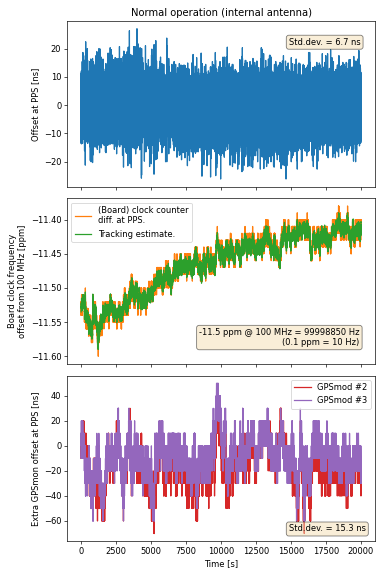
The upper (blue) graph shows the offset of the internal timestamp tracking at each PPS signal.
The middle graph shows the actual internal clock counts (100 MHz) between PPS signals (orange), and the same calculated from the internal tracking adjustment parameter (green).
The lower (red/magenta) graph shows the internal (100 MHz) clock count offset of the PPS signals of two additional GPS modules attached to the same board, relative to the first GPS module. (This allows to get a handle on the GPS module performance without introducing any measurement errors by NTP or PC clocks. Only the direct PPS sampling by the FPGA is used here.)
According to schematics, the oscillator is an ASEM1-100.000MHZ-LC-T which is specified to have a frequency stability of ±50 ppm.
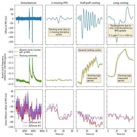
The behaviour when the board 100 MHz oscillator is disturbed by some forced cooling (by blowing air over it), leading to tracking errors of several 100 ns.
The left column is an overview of three disturbances, shown in the next three columns: the second column is for a temporary loss of PPS signal (GPS receiver must have lost satellites). The third column is for periodic (few seconds) cooling. The fourth column is for one longer cooling.
The overall resolution limit seems to be the slow update rate made possible by the 1 Hz discipline from the PPS signal. Luckily (at least this) board oscillator is stable enough to allow good tracking when it (slowly) returns to ambient temperature.
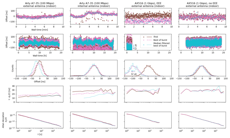
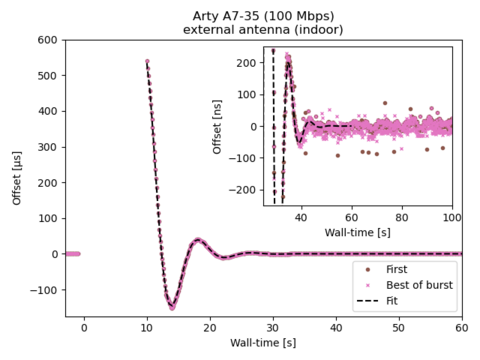
The measurements are performed in rapid bursts, with queries repeated at shorter and shorter intervals, starting with the round-trip time. The total time-span of the burst is a few round-trip times. The circles/solid line (brown) show the first offset measurement in a burst (i.e. not a burst at all). The cross/dashed line (pink) show the result derived from the best combination of transmit and return half of all the measurements in the burst. The plus/dotted line (cyan) has filtered out of each ten successive measurements (i.e. over 10 s) the third lowest round-trip time.
Columns one and two show measurements between two Arty A7-35 boards (100 Mbps) connected by a Netgear FS105 switch. The reference board has an external antenna connected (but located indoors), and so has other board in the pair in first column. The second column shows measurements vs. a board with only the internal antenna of the GPS module.
Columns three and four show measurements between two ALINX AX516 boards (1 Gbps) connected by a Netgear GS105 switch. Both boards have an external antenna connected (but located indoors). For the fourth column, energy-efficient ethernet (EEE) is disabled. When enabled (column three), the effect is surprisingly small in the offset jitter, but leads to approximately 40 μs longer transmission latencies. In burst measurements, i.e. packets sent in rapid succession, the latencies drop for some transmission steps, leading to large shifts.
Rows one and two show measurements as a function of time. The more rapid shifts for an internal antenna (column two) are attributed to more difficulties for the GPS to select satellites with few or no reflections. It should however be noted that a similar amount of maximum deviations are seen for the external antenna case, implying that the even if the short-term variations are smaller, the absolute time offset varies by some 100 ns also in that case.
The third row shows a histogram of the time offsets in row two.
The fourth and fifth rows show the Allen deviation of the measurements.
The serial NMEA messages are parsed to decode the $GPRMC sentences to get time (seconds) and valid fix status.
A fractional increment is used to update the NTP timestamp counter each internal clock cycle (here 125 MHz on the Arty board).
On each PPS signal, the difference between the current NTP timestamp and the expected is calculated. From this, determine a correction to the fractional increment such that the difference calculated in 1 s (the next PPS) would be 0, if all frequencies stay constant. Half of the correction is added to the increment, and the other half is applied only until the next PPS signal.
The NTP status (in the leap seconds field) is reported as unsynchronised whenever no PPS pulses (with a preceding time report with valid fix) has been reported for 2 s. When unsynchronised, the precision is also reported as 127.
The precision field is calculated as the 2-logarithm from a decaying average of the absolute value of the NTP timestamp difference at each PPS signal. The running average decays with 3/4 of the old value retained, and 1/4 of the new difference added. (With the used GPS module, this is typically −27 (2−27 = 7.5 ns), with fluctuations between −26 and −28.)
The table below (work-in-progress!) describes the handling of each octet of all incoming packets, to provide an overview of the (in-)susceptibility to crafted NTP packets. Packets with incoming words that do not match the requirements are dropped, i.e. give no response.
Unless specified, or a checksum, the outgoing (response) packet uses the incoming value for each octet.
| / | Ethernet | ||||||||
|---|---|---|---|---|---|---|---|---|---|
| Offset | E t h e r n e t |
Description | Incoming | Outgoing | Notes | ||||
| 0-5 | MAC destination | Match our MAC | MAC source | ||||||
| 6-11 | MAC source | Any; (broadcast bit 0) | MAC destination (our) | ||||||
| 12-13 | Ethertype | 0x0806 or 0x8035 : ARP 0x0800 : IPv4 |
(as input) | ||||||
| / | ARP | ||||||||
| Offset | A R P |
Description | Incoming | Outgoing | Notes | ||||
| 14-15 | Hardware type | 1 (Ethernet) | (as input) | ||||||
| 16-17 | Protocol type | 0800 (IPv4) | (as input) | ||||||
| 18 | Hardware size | 6 | (as input) | ||||||
| 19 | Protocol size | 4 | (as input) | ||||||
| 20-21 | Operation | 1 (ARP request) | 2 (ARP response) | Cannot make loop. | |||||
| 22-27 | Sender MAC | Target MAC (our) | |||||||
| 28-31 | Sender IP | Target IP (our) | |||||||
| 32-37 | Target MAC | Match our MAC | Sender MAC | ||||||
| 38-41 | Target IP | Sender IP | |||||||
| 42-59 | Padding | 0 | |||||||
| 60-63 | Ethernet FCS (checksum) | Verified | Calculated | ||||||
| / | IPv4 | ||||||||
| Offset | I P v 4 |
Description | Incoming | Outgoing | Notes | ||||
| 14 | Version, Header length | 4, 5 words (= 20 bytes) | (as input) | ||||||
| 15 | DiffServ ECN (congestion) |
0 0 TODO: allow ECN, write 0? |
0 TODO: make configurable (def 0) 0 |
||||||
| 16-17 | Total length | Multiple of 2, < 503. (fakernet limitation) |
(as input) | NTP packets only accepted with payload length 48. |
|||||
| 18-19 | Identification | Any | (High octet as input.) Low octet from counter. |
||||||
| 20-21 | Flags, fragment offset | 0, 0 | (as input) | ||||||
| 22 | Time-to-live | > 0 | TTL - 1 TODO: make configurable | No infinite loop. | |||||
| 23 | Protocol | 01 : ICMP 17 : UDP |
(as input) | ||||||
| 24-25 | IP Checksum | Verified | Calculated | ||||||
| 26-29 | Source IP | Destination IP | |||||||
| 30-33 | Destination IP | Our IP | Source IP | ||||||
| / | ICMP | ||||||||
| Offset | I C M P |
Description | Incoming | Outgoing | Notes | ||||
| 34 | Type | 8 : Echo request | 0 : Echo reply | No loop. | |||||
| 35 | Code | 0 | (as input) | ||||||
| 36-37 | Checksum | Verified | Calculated | ||||||
| 38- | Data | (as input) | |||||||
| / | UDP | ||||||||
| Offset | U D P |
Description | Incoming | Outgoing | Notes | ||||
| 34-35 | Source port | Destination port | |||||||
| 34-35 | Destination port | 123 : NTP | Source port | ||||||
| 36-37 | Length | Match IP length | (as input) | ||||||
| 40-41 | Checksum | Verified | Calculated | ||||||
| / | NTP | ||||||||
| Offset | N T P |
Description | Incoming | Outgoing | Notes | ||||
| 42 | Leap Version Mode |
3 or 4 3 (client) or 4 (server) |
0 or 3 (unsynchronised) 3 -> 4, 4 -> no response |
No loop. |
|||||
| 43 | Stratum | 1 | |||||||
| 44 | Poll | 4 | |||||||
| 45 | Precision | Estimate from GPS tracking. (127 when unsynchronised) |
|||||||
| 46-49 | Root delay | 0 | |||||||
| 50-53 | Root dispersion | Estimate from GPS tracking. (232-1 when unsynchronised) |
Field precision is limited; smallest non-0 value is ≈ 1.52 μ. |
||||||
| 54-57 | Reference ID | GPS\0 | |||||||
| 58-61 | Reference TS | Our latest time fix. | |||||||
| 66-73 | Originate TS | Transmit TS (copy from input). |
|||||||
| 74-81 | Receive TS | Our time at input packet reception. |
|||||||
| 82-89 | Transmit TS | Our time at outgoing packet transmission. |
|||||||
| +4 | Ethernet FCS (checksum) | Verified | Calculated | ||||||
Ping (ICMP echo request and reply)
ping fnet-ntp1.fy.chalmers.se
PING fnet-ntp1.fy.chalmers.se (129.16.110.239) 56(84) bytes of data.
64 bytes from fnet-ntp1.fy.chalmers.se (129.16.110.239): icmp_seq=1 ttl=63 time=0.092 ms
64 bytes from fnet-ntp1.fy.chalmers.se (129.16.110.239): icmp_seq=2 ttl=63 time=0.091 ms
Query the NTP server:
ntpdig fnet-ntp1.fy.chalmers.se
2024-08-09 18:40:08.91746 (+0200) +0.000082 +/- 0.000144 fnet-ntp1.fy.chalmers.se 129.16.110.239 s1 no-leap
Sources are available with the Fakernet sources.
Last modified: Fri Aug 9 18:45:32 CEST 2024